Functional Block Diagram for ADIS16006
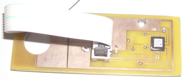
Accéléromètre ADIS16006 monté sur une carte d'acceuil qui déporte la connexion en HE10.
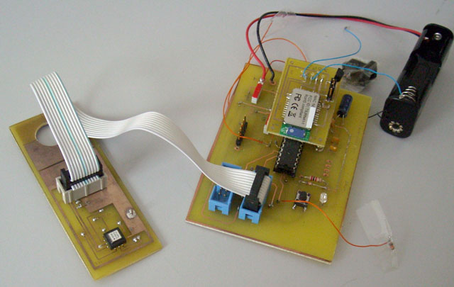
Carte dspic pour tester l'accéléromètre
On remarque le module bluetooth pour une communication des résultats en embarqué.
#define Accel2_Connected |
#define Accel2_Connected ... ... #endif |
#include "p30F3010.h" //#define Accel2_Connected //Configuration bits // Q=10 MHz _FOSC(CSW_FSCM_OFF & XT_PLL8); //10Mhz *8 = 80 MHz /4 = 20 MIPS maxi pour ce pic _FWDT(WDT_OFF); _FBORPOR(PBOR_OFF & BORV_27 & PWRT_16 & MCLR_EN); //Program Specific Constants #define FCY 20000000 //Instruction cycle rate (Osc x PLL / 4) = 20 MIPS #define T1Period 2000 // pour 100 us à 20 MHz : T1Period = 2000=FCY*100 us #define MILLISEC FCY/20000 // 1 mSec delay constant #define tcntPRD 1000 // combien de fois pour arriver en 0.1s avec des pas de 100 us : 1000 #define tcntAccelPRD 10 // combien de fois pour arriver en 1ms avec des pas de 100 us : 10 #define CS_1 _RE0 // Chip select actif à l etat bas du ADIS16006 _1 #define TCS_1 _RE1 // Chip select actif à l etat bas du ADIS16006 _1 Temperature #define CS_2 _RE2 // Chip select actif à l etat bas du ADIS16006 _2 #define TCS_2 _RE3 // Chip select actif à l etat bas du ADIS16006 _2 Temperature #define ST _RD0 // pin de test, 0 = désactivée #define RunningLED _RB0 // Output // prototypes des fonctions void InitVar(); void setup_ports(); void initTimer(); void __attribute__((interrupt, auto_psv)) _ADCInterrupt (); void InitUART(); inline void ConvHexa(int Var, int tablePos, unsigned char * table); inline void ConvDec(int Var, int tablePos, unsigned char * table); inline void ConvDec2(int Var, int tablePos, unsigned char * table); void SendMsg(); void SendData(); void ReceiveData(); void print_LCDbuffer(); void UpdateBufferRunningStatus(unsigned int Status); void CheckSendData(); void DelayNmSec(unsigned int N); struct { unsigned Running : 1; unsigned CheckRX : 1; unsigned SendTX : 1; unsigned SendData : 1; unsigned unused : 12; } Flags; unsigned int AccelX1, AccelY1, AccelX2, AccelY2, Temp1, Temp2; unsigned int tcntAccel, ReaderFlagXY; unsigned int tcnt, heure, min, sec, dsec, TimeStamp; // RS232 ------------------------------------------- unsigned char *TXPtr; unsigned char *RXPtr; #define CR 0x0D #define LF 0x0A #define BAUD 57600 // for BT unsigned char InData[] = {"000000000000000000000000000000000"}; //unsigned char current_inputindex; #define current_inputindexLimit 31 unsigned char OutData1[] = {"$AcX1=0000 AcY1=0000 T1=0000 T1=+000.00 :R Ts=0000\r"}; unsigned char OutData2[] = {"$AcX2=0000 AcY2=0000 T2=0000 T2=+000.00 :R Ts=0000\r"}; #define OffsetAccelX1 6 // offset in OutData : position de la val de Bref #define OffsetAccelY1 16 // offset in OutData : position de la val de Bmes #define OffsetT1 24 // offset in OutData : position de la val de Temperature 1 #define OffsetT1dec 32 // offset in OutData : position de la val de Temperature 1 en decimal #define Stateoffs 41 // offset in OutData : position de la val de Running #define OffsetTs 46 // offset in OutData : position de l offset int SeqComm; // ttes les 0.5 s #define SeqCommMax 5000 |
//----------------------------------------------------------------------------- // Setup ports //----------------------------------------------------------------------------- void setup_ports() { ADPCFG = 0xFFFF; // all PORTB = Digital(1), no analog inputs(0) ie 1111 1111 // Clear All Ports Prior to defining I/O PORTB=0; //Initialize LED pin data to off state PORTC=0; PORTD=0; PORTE=0; // Now set pin direction registers TRISB = 0xFFFC; // RunningLED RB0 out, RB1 NC out, RB2-5 NC inputs in xx11|1100 TRISC = 0xFFFF; // U1ATX/RC13 in , U1ATX/RC14 out INUTILE de les configurer ainsi car directement on configure l UART TRISD = 0xFFFC; // ST RD0 Out, NC RD1 Out xxxx|xx00 TRISE = 0x01C0; // RE0-5 are the CS and TCS outputs, RE8 NC(SCLK/SPI) in 1|xx00|0000 TRISF = 0xFFFF; // RF NC(PGC/SPI) input CS_1 =1; TCS_1=1; CS_2 =1; TCS_2=1; // debug test // ST=1; // Accel ADIS 16006 en mode test ST=0; // Accel ADIS 16006 en mode normal (pas de test) // Init SPI // SPI1CON = 0x006D; // Master mode, SCK = Fcy/12 = 20/3/4=0.25 MHz, SMP=0, CKP=1(Clk idle is high), CKE=0, 8 bits // SPI1CON = 0x0076; // Master mode, SCK = Fcy/12 = 20/3/4=1.66 MHz, SMP=0, CKP=1(Clk idle is high), CKE=0, 8 bits 0|0111|0110 SPI1CON = 0x006E; // Master mode, SCK = Fcy/12 = 20/5/4=1.66 MHz, SMP=0, CKP=1(Clk idle is high), CKE=0, 8 bits 0|0111|0110 //bit 9 SMP: SPI Data Input Sample Phase bit // Master mode: // 1 = Input data sampled at end of data output time // 0 = Input data sampled at middle of data output time //bit 8 CKE: SPI Clock Edge Select bit // 1 = Serial output data changes on transition from active clock state to Idle clock state (see bit 6) // 0 = Serial output data changes on transition from Idle clock state to active clock state (see bit 6) // Note: The CKE bit is not used in the Framed SPI modes. The user should program this bit to 0 for the //bit 6 CKP: Clock Polarity Select bit // 1 = Idle state for clock is a high level; active state is a low level // 0 = Idle state for clock is a low level; active state is a high level //bit 5 MASTER ENabled = 1 //bits 4,3,2 SPRE scaler //bits 1,0 PPRE scaler SPI1STAT = 0x8000; // Enable SPI port } |
//------------------------------------------------------------------------ void __attribute__((interrupt, auto_psv)) _T1Interrupt( void ) { RunningLED=1; IFS0bits.T1IF = 0; // lit les accelerateurs ReaderFlagXY = (++ReaderFlagXY) & 1; ReadAccel(); if (++tcntAccel>=tcntAccelPRD) // le timer des milisecondes { tcntAccel=0; // ttes les 1 ms ReadTemp(); } if (++tcnt>=tcntPRD) // le timer des milisecondes { tcnt=0; if (++dsec==10) { dsec=0; if (++sec==60) { sec=0; if (++min==60) { min=0; if (++heure==24) heure=0; } } } } // communication dsPIC -> PC if (!--SeqComm) { // debug Attention, AccelXi a eu le tps de changer entre temps ! TimeStamp++; SeqComm=SeqCommMax; Flags.SendData=1; } RunningLED=0; } |
//------------------------------------------------------------------------ // La routine commande la conversion pour le prochain appel et lit // le resultat correspondant à ce qui a déjà été converti entre tps //------------------------------------------------------------------------ void ReadAccel() { unsigned int dum1, dum2; SPI1STATbits.SPIROV = 0; // Clear overflow flag // on lit le 1er accéléromètre : axe alpha CS_1=0; // Accelerometre 1 actif if (ReaderFlagXY) SPI1BUF = 0x0C; // demande la conversion de AccelY else SPI1BUF = 0x04; // demande la conversion de AccelX while (SPI1STATbits.SPITBF); while ( !SPI1STATbits.SPIRBF); // write and read 8 bits dum1 = SPI1BUF; SPI1BUF=0x00; while (SPI1STATbits.SPITBF); while ( !SPI1STATbits.SPIRBF); // dummy write to read 8 low bits dum2 = SPI1BUF; if (ReaderFlagXY) AccelX1 = ((dum1 << 8) & 0x0F00) | (dum2 & 0xFF); else AccelY1 = ((dum1 << 8) & 0x0F00) | (dum2 & 0xFF); __builtin_nop(); CS_1=1; // Accelerometre 1 inactif // on lit le 2eme accéléromètre : axe beta #ifdef Accel2_Connected CS_2=0; // Accelerometre 2 actif if (ReaderFlagXY) SPI1BUF = 0x0C; // demande la conversion de AccelY else SPI1BUF = 0x04; // demande la conversion de AccelX while (SPI1STATbits.SPITBF); while ( !SPI1STATbits.SPIRBF); // write and read 8 bits dum1 = SPI1BUF; SPI1BUF=0x00; while (SPI1STATbits.SPITBF); while ( !SPI1STATbits.SPIRBF); // dummy write to read 8 low bits dum2 = SPI1BUF; if (ReaderFlagXY) AccelX2 = ((dum1 << 8) & 0x0F00) | (dum2 & 0xFF); else AccelY2 = ((dum1 << 8) & 0x0F00) | (dum2 & 0xFF); __builtin_nop(); CS_2=1; // Accelerometre 2 inactif #endif } |
//------------------------------------------------------------------------ void ReadTemp() { SPI1STATbits.SPIROV = 0; // Clear overflow flag // Read Temperature 1 TCS_1=0; // Temperature 1 actif SPI1BUF=0x00; while (SPI1STATbits.SPITBF); while ( !SPI1STATbits.SPIRBF); // write and read 8 hi bits Temp1=SPI1BUF<<8; SPI1BUF=0x00; while (SPI1STATbits.SPITBF); while ( !SPI1STATbits.SPIRBF); // dummy write to read 8 low bits Temp1 |= SPI1BUF & 0xFF; Temp1 = (Temp1 >>5) & 0x03FF; TCS_1=1; // Temperature 1 inactif // Read Temperature 2 #ifdef Accel2_Connected TCS_2=0; // Temperature 2 actif SPI1BUF=0x00; while (SPI1STATbits.SPITBF); while ( !SPI1STATbits.SPIRBF); // write and read 8 hi bits Temp2=SPI1BUF<<8; SPI1BUF=0x00; while (SPI1STATbits.SPITBF); while ( !SPI1STATbits.SPIRBF); // dummy write to read 8 low bits Temp2 |= SPI1BUF & 0xFF; Temp2 = (Temp2 >>5) & 0x03FF; TCS_2=1; // Temperature 2 inactif #endif } |
Last update : 11/02/2009